Printed circuit boards designed for aerospace and military applications shall have a high degree of reliability and robustness, without offering any margin for error. Challenging applications, such as space missions, require an accurate understanding of how printed circuits must be designed and created to ensure a very long period of operation, in often very extreme operating conditions. Unlike most traditional PCBs, printed circuit boards used in aerospace applications are subjected to extreme environmental conditions, radiation, chemicals, contaminants, and more.
It follows that these circuits must meet very strict standards, such as the IPC-A-610E Class 3, which refers to high-performance electronic devices whose operation must be guaranteed continuously, without any interruption, even in the most difficult and critical operating conditions. Some of the main applications falling within the scope of the IPC-A-610E Class 3 standard are the following:
- systems for satellite communication
- navigation systems, control systems and on-board avionic instrumentation
- applications for on-ground processing of data recorded during flights or missions (ground stations)
- passive detection systems
- UAVs (Unmanned Aerial Vehicles)
Circuits for aerospace applications are exposed to extreme temperatures and must be able to withstand and absorb shocks and vibrations of considerable intensity. In addition, they have many features in common with PCBs for RF high frequency applications, bearing in mind that radio communication in the HF (or higher) band is a fundamental requirement for these systems. Operating at high altitudes, the risk associated with radiation also increases and, as a result, PCBs (as well as the electronic components used) must be designed to withstand high levels of radiation for a long time without being damaged.
In the next paragraphs some of the most common guidelines and recommendations will be presented to assist the designer in the delicate, but also rewarding and satisfying, task of designing a PCB for aerospace use.
and get your PCBA quote within the next 10 minutes!
1 – Select high quality materials
In the aerospace sector, reliability and durability are two requirements that cannot be ignored. In this type of applications, the circuits must operate continuously and without incurring malfunctions for long periods of time (generally from a minimum of 5 years up to 15 years or more), considering that maintenance interventions are not possible or have exorbitant costs. The general rule is to use high quality materials and components, which remain available on the market for long periods of time.
A very common alternative to copper is represented by anodized aluminum, capable of solving many of the problems related to heat dissipation. In fact, anodized aluminum offers a thermal conductivity from 5 to 10 times higher than traditional materials such as FR-4, with a thickness of ten times less. Furthermore, it is able to transfer heat in a exponentially more efficient way than a conventional PCB and minimizes the effects of heat-induced oxidation.
2 – Use heavy copper technology
Heavy copper technology, with copper thicknesses ranging from 2 to 6 oz/ft2 (or more), allows heat dissipation in a natural way, without requiring additional cooling systems even in the presence of high intensity currents. Many manufacturers suggest combining heavy copper solutions with the inclusion of numerous thermal vias to further improve heat dissipation. Figure 1 shows the detail of a multilayer PCB with heavy copper layer.
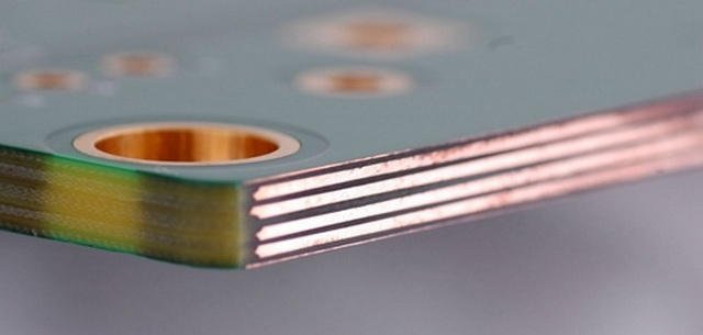
Figure 1: PCB with heavy copper layer.
3 – Adhere to reference standards
PCBs for the aerospace industry must operate with minimal maintenance and must meet rigorous safety and quality standards. For this reason, designers and manufacturers of PCBs for aerospace applications must follow a specific set of reference standards. The reference standards include the IPC 6012DS, an addendum to the IPC-6012D standard that provides qualification and performance requirements for rigid printed circuit boards for aerospace and military applications. This standard can be considered as an enhanced version of the IPC Class 3 standard.
Very important is also the aerospace standard AS/EN 9100, which contains a series of standards developed by the IAQG (International Aerospace Quality Group) for quality and risk management in the aerospace sector. This standard is internationally adopted and represents the quality management system applicable to the aerospace industry. Compared to the ISO9001 standard, with which it shares many common parts, the AS/EN 9100 standard introduces additional requirements created specifically for the aerospace context. PCBs designed for this type of application must conform to the standard and be accompanied by a certification attesting the quality of the manufacturing process.
4 – Provide an excellent thermal management
As mentioned above, aerospace PCBs must ensure excellent heat dissipation, without requiring the use of external heatsinks. In addition to heavy copper technology and the extensive use of thermal vias, special solutions based on materials such as Pyralux AP, FR408, and other metal materials and components can be used. Compared to traditional PCBs, it is also preferable to increase the distance separating the components, which can thus have a greater volume of space for heat dissipation.
5- Use conformal coating
PCB finishing materials should be chosen to withstand the extreme operating conditions under the harshest operating conditions. The main conformal coating techniques include electrolytic nickel gold, ENIG (Electroless Nickel with Immersion Gold Coating), chemical silver, HASL (Hot Air Solder Leveling) and lead-free HASL. The application of the conformal coating provides protection against heat, humidity, water and vibrations, all conditions that can be encountered in aerospace applications. Conformal coating should also be followed by the application of acrylic-based spray in order to protect the final printed circuit from contamination or accidental short circuits. Figure 2 shows the detail of a PCB with HASL conformal coating.
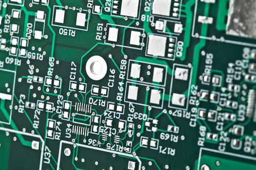
Figure 2: PCB with HASL conformal coating.
6 – Routing guidelines
Size of PCB traces should be chosen to handle the maximum current load, ensuring excellent heat dissipation in all operating conditions. As occurs in circuits with high frequency signals, the angles on the traces must be less than 45°, thus favoring the uniform and regular transmission of the signal throughout the circuit. Electronic components that operate at low frequencies should be separated from those that use high frequencies. The latter, in fact, can generate waveforms and disturbances capable of influencing the operation of low frequency components. The waveforms and noise cause a degradation of the signal quality, compromising the integrity of the signal which is a mandatory requirement for these applications. The clock signals must be provided with appropriate physical shielding, created during the design phase by applying casings made of aluminum or similar materials. As happens in any RF printed circuit, the rules must also be applied to reduce or limit the crosstalk phenomena between adjacent traces.
7 – Use of flex and rigid-flex PCBs
Very common in satellite and avionics systems are flexible (Figure 3) and rigid-flexible printed circuit boards, with the difference that, compared to industrial or automotive applications, they are mainly manufactured with polyamide instead of FR-4. This material has the characteristic of easily adapting to small spaces, it is very light and resistant to heat and chemical agents and guarantees a high durability.
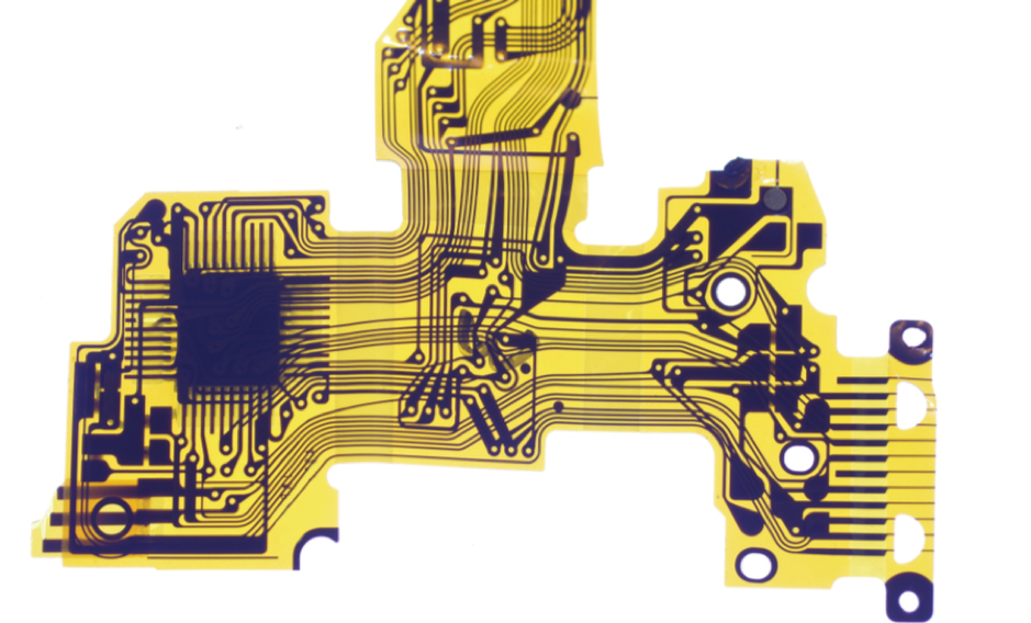
Figure 3: Flexible printed circuit board (source: Altium).
Flex and rigid-flex PCBs are widely used in the aerospace industry by virtue of their ability to adapt to small spaces, high resistance to vibrations, shocks, temperature and external agents, excellent mechanical and electrical connection, low weight. Rigid-flex PCBs are composed of a combination of rigid and flexible printed circuit boards, permanently connected to each other. The correct use of flex and rigid-flex PCBs offers an optimal solution for difficult and limited space applications. This technology offers a secure connection between the various parts of the circuit, ensuring both polarity and contact stability and reducing the number of connectors.
Conclusion
Printed circuits for the aerospace sector, and more generally all electronic circuits that must meet the IPC-A-610 Class 3 and 3A standard, must be designed from the outset with the aim of obtaining high electrical reliability, especially in the most difficult and unconventional operating conditions. PCB design, starting with selecting the most suitable materials to withstand extreme environmental conditions with continuous failure-free operation, represents a very ambitious challenge for every electronic designer. In this article, some useful guidelines have been presented to better understand the issues and provide a reference point for the design of printed circuit boards for aerospace applications.