Regardless of its type (rigid, flexible, or rigid-flex), each printed circuit requires a physical support, also known as a substrate, on which to place the components and make the necessary connections between them. The type and technical characteristics of the substrates used for PCB fabrication represent one of the first challenges that the designer must face, it is the first step towards the construction of a high quality PCB.
The type and characteristics of the substrate directly affect the performance of the PCB. For example, a rigid substrate increases both the strength and durability of the PCB, while a flexible substrate gives the engineers more design options.
The substrate is essentially a non-conductive material, often selected on the basis of the value of its dielectric constant (Dk). Substrates are dielectric composite structures made from epoxy resin and glass or paper fabric. Sometimes, substrates are supplemented with specific materials, such as ceramic, to improve their dielectric constant. The printed circuit board industry is constantly evolving, with the consequent introduction of many different types of substrates, from solid glass fiber to flexible polymers. Historically, fiberglass has been the most common form of substrate, being a low cost and highly reliable material that provides a good solid base for the PCB.
Figure 1 shows the typical stackup of a multilayer PCB. The two external sides, as well as two internal layers (usable as ground planes, power supply, or for the layout of the traces) are made from copper foils. The innermost layer (the core) is made with pre-preg, while the other two layers are the substrates.
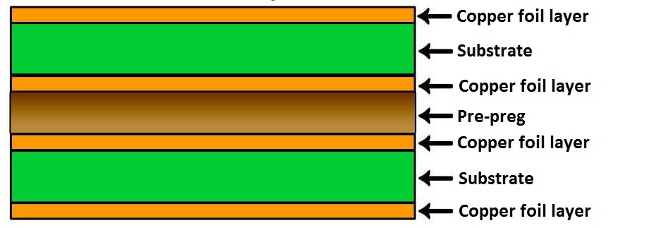
Figure 1: typical structure of a multilayer PCB
Technical characteristics
Materials and substrates used for PCB manufacturing shall provide high strength and reliability, as the correct operation and duration of the electronic circuit depend on their performance. The main technical characteristics that determine the quality of a substrate are the following:
- dielectric constant
- thermal conductivity
- thermal expansion coefficient
- maximum operating temperature (MOT)
- electrical insulation.
The dielectric constant, also known as electrical permittivity of a material (symbol Ɛ), expresses its ability to store electrons in an electric field. This characteristic is fundamental for the substrates used in power electronics, as the high voltages and currents to which the power devices are subjected produce non-negligible electromagnetic fields. These high intensity electromagnetic fields can in fact induce currents in adjacent traces if the dielectric constant is too high. Substrates with a higher dielectric constant must be fabricated with greater thicknesses than substrates with a lower dielectric constant to achieve the same capacitance value. Therefore, the use of lower dielectric constant materials can lead to a reduction in the size and weight of a substrate. In addition, substrates with lower dielectric constant allow designers to reduce the distance between traces, thus resulting in a smaller circuit.
The thermal conductivity of a material (also known as thermal resistance) measures its ability to transfer heat. Expressed in watts per Kelvin meter (W/mK), thermal conductivity indicates how efficiently the material conducts heat through its volume. Thermal conductivity is another relevant parameter for substrates, especially if the heat produced by high-power devices needs to be transferred to a heatsink or to a ground plane. If the thermal conductivity is too low, heat may build up around particular components, causing high temperatures that affect performance and could cause malfunction or damage.
The coefficient of thermal expansion (CTE) measures the ability of a material to change its size according to the temperature to which it is subjected. At the same temperature, a substrate with a high CTE will undergo greater expansion than a substrate with a low CTE. The CTE of a substrate plays a fundamental role in multilayer PCBs. In fact, if the substrates that make up the various layers have different CTEs, a detachment could be created between the layers themselves when the PCB is subjected to temperature cycles. As temperature rises, the high CTE substrate can expand with a force greater than its mechanical strength, resulting in cracks, chips or other mechanical damage.
The maximum operating temperature (MOT) of a substrate represents the temperature value up to which it maintains the characteristics specified by the manufacturer; above this temperature threshold, the substrate will have a higher chance of failure. Normally, the substrate manufacturer specifies both the MOT value and the time during which this limit temperature can be maintained without causing damage.
The electrical insulation of a substrate indicates how badly it conducts electricity. This characteristic, also known as bulk resistivity (BR), measures the amount of electrons being conducted through a material. The greater the bulk resistivity of a substrate, the better is its ability to prevent the generation of floating currents within the material. The insulation capacity of a substrate is strictly dependent on the thickness. It follows that, with the same total insulation, a substrate with high bulk resistivity will presumably have a lower thickness than a substrate with lower bulk resistivity.
Main types of substrate
Materials used for PCB manufacturing are of fundamental importance, as they shall provide outstanding characteristics and properties, such as resistance to temperature, adhesion, tensile strength, flexibility, dielectric strength, dielectric constant, and more. The performance, reliability and lifetime of the PCB strictly depend on the materials used to manufacture the substrates.
FR-2
FR-2 is probably the type of substrate that offers the lowest performance. Although it is flame retardant (FR-2 means Flame Retardant Level 2), FR-2 is composed of a phenolic material, which is a particular type of impregnated paper deposited on top of a glass fiber. This substrate is now only used in some very economical consumer applications, such as small low cost radios.
FR-4
It is the most widely used material for manufacturing PCB substrates. It is composed of a glass reinforced epoxy laminate sheet. The epoxy resin used is fireproof (FR-4 means Flame Retardant Level 4), water resistant and does not absorb moisture. The tensile strength is very high, as well as the strength/weight ratio and the electrical insulation. There are several types of FR-4 which, in addition to the common characteristics mentioned above, differ in some specific properties, such as:
- standard FR-4: it is the most common and economical type of FR-4, with a heat resistance up to 140°C - 150°C
- FR-4 for high temperatures (high Tg): this version of FR-4 offers a high value of Tg (glass transition temperature), which allows the substrate to reach temperatures up to 1180°C
- FR-4 halogen-free: it is a version of material with a low content of halogens (which develop toxic substances during burning). Halogens are among the most widely used fireproof elements.
PTFE (Teflon)
PTFE is a type of plastic that offers no resistance and is therefore only used in applications with high speed and high frequency signals. PTFE is extremely flexible, making it valuable in tight tolerance applications, and offers a high degree of insulation. It is also extremely light, flame resistant, offers high mechanical strength and maintains its stable characteristics as the temperature changes. Due to its excellent high-frequency characteristics, it is used in electronic devices that handle signals from several hundred MHz to several tens of GHz.
Metal substrates
Metal substrates, typically made of aluminum, offer high dielectric and thermal properties and expand slowly. Aluminum ensures excellent high frequency performance and can easily withstand temperatures up to 350°C. Directly connected to the aluminum substrate is the ceramic substrate, obtained through an electro-chemical process that creates a dielectric layer of aluminum oxide crystals directly on the surface of an aluminum substrate. Since the thickness is much thinner than standard substrates, this material achieves higher dielectric thermal conductivity than conventional dielectric materials currently used for PCBs. The aluminum substrate offers excellent high frequency performance, yet at a higher cost than other solutions. It is used in microwave equipment, in the RF sector, in wireless communication base stations and in PCBs for LED lighting.
LTCC
Acronym for Low Temperature Co-fired Ceramics, LTCC is a type of substrate used mainly in multilayer PCBs. Since the aluminum oxide used for its manufacture must be burnt at a high temperature (1500°C), it is not possible to perform simultaneous burning with the layers containing the traces made with low melting copper. By adding glass-based materials to aluminum oxide, LTCC substrates can be burnt at temperatures up to 900°C. This allows for simultaneous burning with a low-melting circuit layout, such as copper or silver. This type of substrate is widely used in high frequency RF modules.
Flexible substrates
Flexible substrates can be easily folded, or wrapped into the desired shapes, without compromising the electrical continuity of the circuit in any way. This allows designers to make PCBs that adapt to even the smallest spaces or to enclosures with irregular shape. Instead of fiberglass or epoxy resins, these substrates use particular types of plastic films. Flexible substrates can be made with materials such as polyimide and LCP (liquid crystal polymer), or with low-cost materials such as polyester and PEN. Since flexible substrates are very thin, their production requires very specialized equipment and processing, with higher costs than other materials. Figure 2 shows an example of PCB made with flexible substrates.
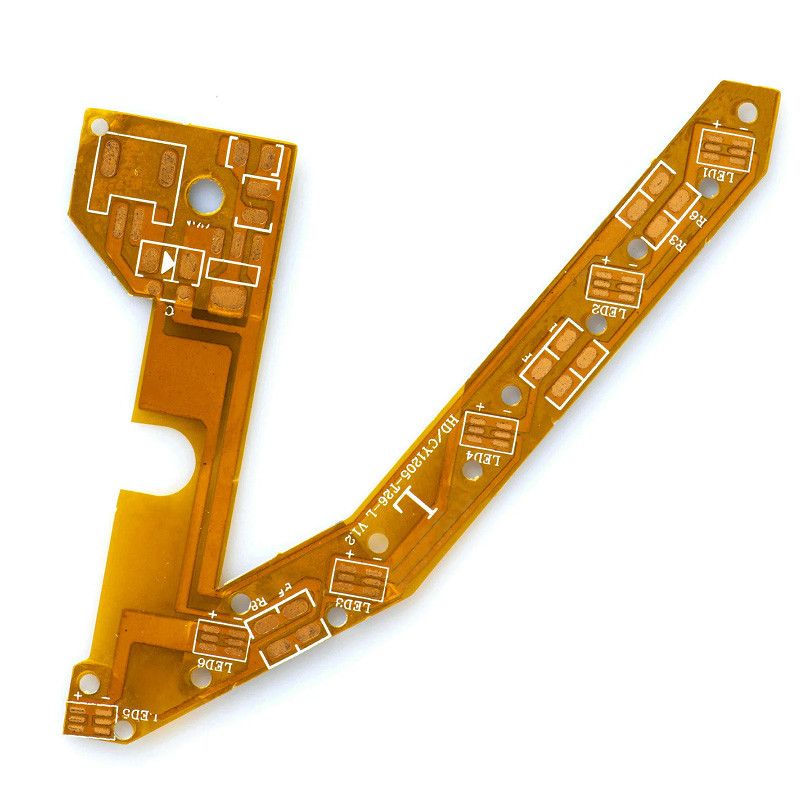
Figure 2: Flexible PCB
Commonly abbreviated as PI, polyimide is a polymer with excellent properties such as thermal stability, thermal resistance, excellent electrical properties and excellent chemical resistance. A polyimide film called Kapton (introduced by DuPont Corporation) is found in most flexible PCBs available on the market. Kapton possesses particular qualities, such as high heat resistance, robustness and a dielectric constant of only 3.6.
Rigid-flex substrates
They are obtained by combining flexible and rigid substrates. For example, a PCB may comprise multiple layers of polyimide attached to a rigid ceramic layer. PCBs made with this material are widely used in critical applications in the medical, aerospace, aeronautical and military sectors, where requirements such as reliability, robustness, mechanical resistance and high temperatures are very strict.
28.03.2022
and get your PCBA quote within the next 10 minutes!