When power-system designers start a new AC-DC power converter design, they are faced straight away with the important choice of topology. Broadly seven different topologies at least are supported by suppliers of power controller ICs. Each has a different set of advantages and drawbacks. So what is the best way to choose the topology for any given application?
This article provides guidelines to help narrow down the range of topologies selected for detailed evaluation. Using guidelines such as these, designers will find that they can streamline their research and more effectively make a sound choice of topology at the outset of a new project.
As any experienced power designer will acknowledge, however, history is littered with examples of failed or delayed projects, the downfall of which may be attributed directly to decisions made at the start of the project. Before introducing the best practice guidance on topology evaluation, it is worth understanding first the factors that undermine AC-DC converter designs at their earliest stage.
The causes of misjudgement about topology
In this author’s experience, the most common causes of design failure in AC-DC converter projects have their roots in either technical misjudgement or human behaviour.
On the technical side, inexperienced designers are prone to using a crude rule-of-thumb based on the maximum power loading that the converter is required to support. Power rating is of course an important parameter – but it is by no means the only one which is affected by the choice of topology.
System size and weight, system cost, power efficiency, thermal efficiency, complexity and EMI are all factors that the designer can optimise for with the right topology. It should also be recognised that these factors are inter-dependent. For instance, a complex Zero-Voltage Switching (ZVS) topology will produce far less severe EMI effects than a simpler hard-switched scheme. The choices made at the outset of a design should not only reflect the technical specifications of the product design, but also the capabilities of the development team and the design time available to it. A development team which has deep expertise in EMI mitigation and EMC compliance, for instance, might be happy to employ a hard-switched topology in place of the complex ZVS alternative.
The other factor which in practice undermines good topology selection is human nature. It is common – and all too understandable – to rush the initial topology choice in order to more quickly progress to hardware development. This is often because a manager can see – and potentially be impressed by – a working prototype: it is a visible sign of progress with the project. The truth is, as well, that designing circuits and building boards is more fun and interesting than doing paper research into topologies.
Another human failing common among engineers bedevils power-system design projects: a preference for solitary technical problem-solving over collaborative activities and teamwork. A choice of topology normally calls for careful weighting of the various trade-offs at the system level. For instance, a decision which reduces Bill-of-Materials (BoM) cost but increases a converter’s size and weight might affect logistics arrangements and raise shipping costs for the end product as a whole – factors which go far beyond the management authority of the engineering department. A holistic view of all costs across the entire product life cycle could help the design engineer to make better and more informed component choices.
Overall, experience suggests that failure to take into account the wider commercial environment can lead to project delays or even cancellation.
Avoiding early mistakes in power design projects
The question that arises from the above discussion is, how best to avoid this kind of mistake?
The obvious answer is of course to do the reverse of the flawed approaches:
- Collaborate extensively with colleagues across departments to gain relevant input on all the factors affected by the choice of topology
- Perform in-depth research into all applicable topologies, weighing up all the factors which are affected by the choice.
This second recommendation can appear challenging because there are so many choices of topology to evaluate. In fact, it is not as daunting as it might seem at first sight, because for any given power rating it is normally possible to narrow the choice down to two or three suitable topologies.
Table 1 is intended to facilitate this first-level evaluation: it provides a score for each topology on each engineering factor that should be considered, where the best topology has a score of 5 and the worst a score of 1. The scores provide a rough indication, and experienced power-system designers might dispute one score or another. Overall, however, the table provides a useful guide to orientate the evaluation process and to inform the designer’s discussion of trade-offs with colleagues.
| Power Level |
Topology | Efficiency | Complexity | EMI | Size/Power Density |
Cost | Power Facture Correction |
|
< 100 W |
Flyback |
2 |
5 |
2 |
5 |
5 |
Aucun PFC < 75 W, CrCm > 75 W |
|
100-150 W |
Flyback |
2 |
5 |
2 |
5 |
5 |
CrCm |
|
Forward |
3 |
4 |
3 |
3 |
3 |
CrCm |
|
|
150-200 W |
Forward |
2 |
4 |
3 |
3 |
3 |
CrCm |
|
LLC Resonant |
4 |
1 |
5 |
4 |
1 |
CrCm |
|
|
200-250 W |
Forward |
2 |
4 |
2 |
2 |
4 |
CrCm/CCM |
|
2-Switch Forward |
3 |
3 |
3 |
3 |
3 |
CrCm/CCM |
|
|
LLC Resonant |
4 |
1 |
5 |
4 |
1 |
CrCm/CCM |
|
|
250-300 W |
Forward |
2 |
4 |
2 |
2 |
4 |
CrCm/CCM |
|
2-Switch Forward |
3 |
3 |
3 |
3 |
3 |
CrCm/CCM |
|
|
LLC Resonant |
4 |
1 |
5 |
4 |
2 |
CrCm/CCM |
|
|
Half Bridge |
4 |
2 |
3 |
2 |
2 |
CrCm/CCM |
|
|
300-400 W |
2-Switch Forward |
2 |
3 |
2 |
3 |
4 |
CCM |
|
LLC Resonant |
5 |
1 |
5 |
5 |
2 |
CCM |
|
|
Half Bridge |
4 |
2 |
3 |
3 |
2 |
CCM |
|
|
400-500 W |
LLC Resonant |
5 |
2 |
5 |
5 |
2 |
CCM |
|
Half Bridge |
4 |
3 |
3 |
3 |
3 |
CCM |
|
|
500-600 W |
Half Bridge |
3 |
3 |
3 |
3 |
3 |
CCM/Interleaved |
|
Full Bridge |
5 |
2 |
3 |
2 |
2 |
CCM/Interleaved |
|
|
600-800 W |
Full Bridge |
4 |
2 |
3 |
3 |
2 |
Interleaved |
|
Phase Shift ZVT |
5 |
1 |
4 |
4 |
1 |
Interleaved |
|
|
> 800 W |
Phase Shift ZVT |
5 |
1 |
4 |
4 |
1 |
3-Phase Interleaved |
Table 1: rankings of various AC-DC power converter topologies. In the power factor correction column, CrCM = Critical Conduction Mode, and CCM = Continuous Conduction Mode
and get your PCBA quote within the next 10 minutes!
Impact of new technology options
Beyond the choice of topology, there is one other important element of a designer’s research before embarking on hardware implementation: the discovery of new components or technologies that have altered the landscape since earlier design projects were implemented.
Today, for instance, many AC-DC converter designers should be considering the use of new wide bandgap silicon carbide (SiC) or gallium nitride (GaN) power components, which support much faster switching than silicon equivalents and can operate at higher temperatures.
If the design priority is to achieve small size and weight and high power density, these characteristics become especially attractive. SiC MOSFETs, available today in production volumes from suppliers such as STMicroelectronics, ROHM Semiconductor and Microsemi (now a Microchip company), enable the use of smaller capacitors and inductors, reducing the size of the complete converter assembly. The higher maximum operating temperature of SiC devices can also sometimes allow the designer to eliminate a fan or heat-sink that would have been required in a design using silicon MOSFETs, even in a densely populated enclosure with limited circulation of cooling air flows.
X-Gan GaN High Electron Mobility Transistors (HEMTs) from Panasonic provide similar advantages in the GaNdalf reference design board from Future Electronics (see Figure 1). This design demonstrates the bridgeless totem pole topology in the Power Factor Correction (PFC) stage of a <1kW AC-DC power supply. The use of GaN transistors helps the circuit to achieve high efficiency of better than 99.0% in the PFC stage.
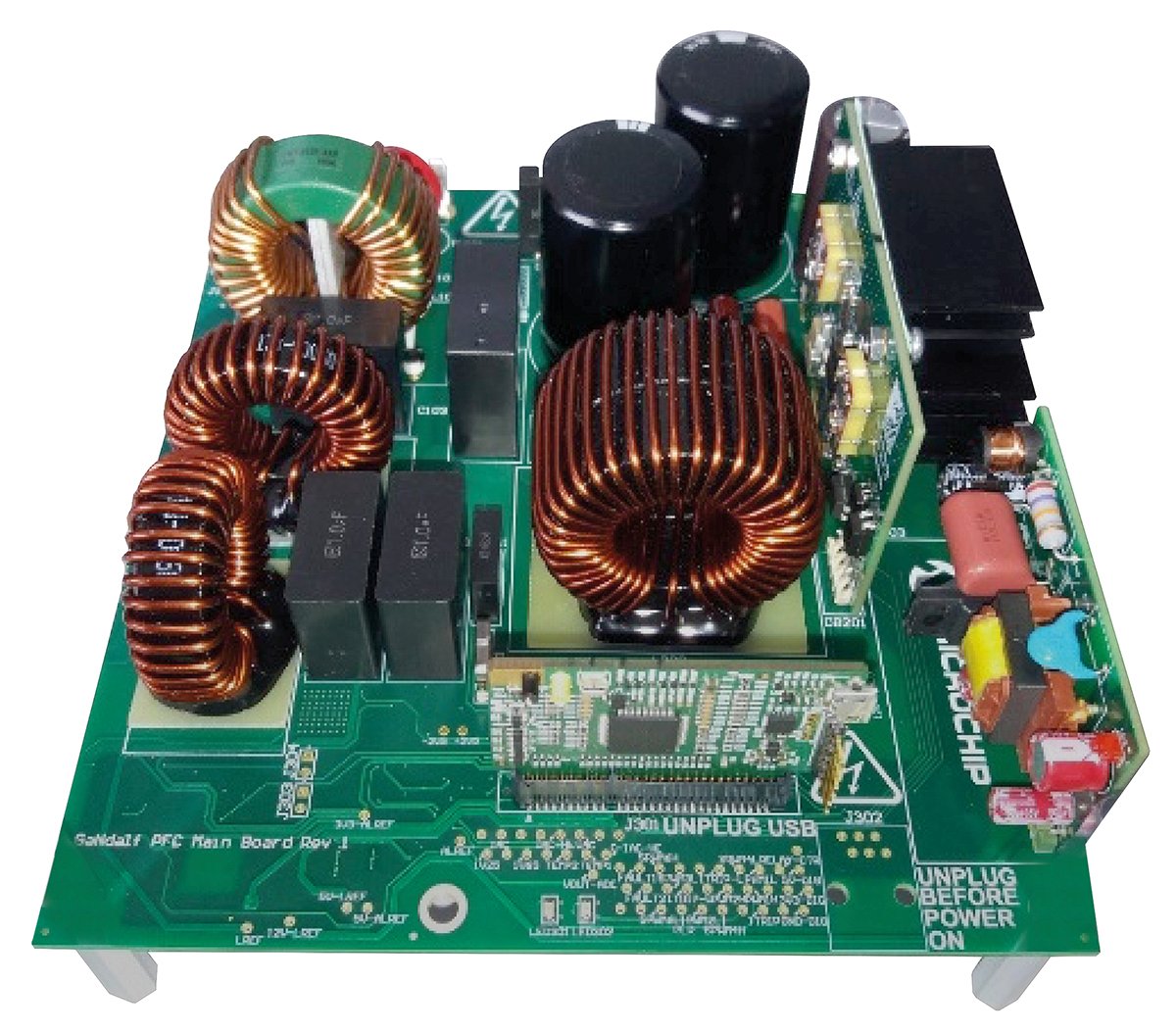
Fig. 1: the GaNdalf AC-DC power supply reference design board from Future Electronics
The other important new product concept to affect AC-DC converter design today is the integration of the primary and secondary controller in a single IC for converters supplying less than 80W. This approach is enabled by an innovative power controller IC from Monolithic Power Systems. The MPX2001 provides a fully integrated solution for flyback converter designs.
It is a flyback controller with integrated primary and secondary control, and a synchronous rectification driver with capacitive isolation. Using the MPX2001, system complexity can be reduced since no feedback circuit is needed. This also has the effect of reducing total BoM cost. At the same time, a synchronous rectifier can be matched perfectly with the driving signal of the primary-side MOSFET. With this feature, the rectifier can operate safely in continuous conduction mode, which helps increase overall efficiency and provides the design with more flexibility.
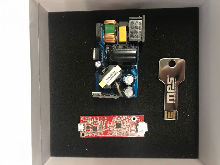
Fig. 2: the MPX2001 evaluation kit, a small design intended as a demonstation of a computer or smartphone power adaptor or charger. (Image credit: Monolithic Power Systems)
The high efficiency of MPX2001-based AC-DC converters is demonstrated by the EVKT-MPX2001-45-PD evaluation kit from Monolithic Power Systems (see Figure 2). This is a design for a 45W USB Power Delivery power adapter intended to transfer power via a USB Type-C connector. It far exceeds the efficiency requirements of the US Department of Energy's Level VI and the European CoC Tier 2 standards. No-load power consumption is <0.075W.
Combining improved component technologies, comprehensive consideration of the contrasting advantages and drawbacks of each converter topology, and an understanding of the requirements of other departments beyond the engineering lab, power-system designers can give their projects the best chance of reaching a successful conclusion – as well as of meeting or exceeding the end product’s design specifications.
By Riccardo Collura.
Northern Europe Power Specialist Field Application Engineer, Future Electronics
www.futureelectronics.com

-1.png)