Before the affirmation of Gerber files, there was no standard guideline to follow for the production of printed circuit boards (PCB). The documents that embraced the PCB specifications followed diversified content. Graphic, textual, descriptive, bitmap and vector formats described and well represented the final project but, often, incompatibilities of measurements, dimensions, positioning and more occurred. Many times there was confusion and misunderstanding between customers and production companies. With the adoption of the Gerber format, finally, there is a universal compatibility between PCB designers and their manufacturers. In this way the latter can operate with a file format that is completely independent from the CAE/CAD software used.
The Gerber format
This format does not identify a single document but constitutes the standard for the production of printed circuit boards. The different files, exported at the end of a project, contain descriptions of the electrical connections, the tracks, the vias and the pads. These are vector documents made up of a set of commands that generate a flow of graphic objects. They also include the instructions for the holes to be made on the PCB. Nowadays, the companies that produce the printed circuit boards only require customers for this type of documentation, nothing else. The most important electronic design software contain and provide the possibility to export the entire work in this format. Therefore having this available is the first thing that an electronic designer should check in his CAE software. Currently the standard format used is RS-274X. It is an extremely powerful version as it includes, in the same document:
- the configuration parameters;
- the openings;
- the XY coordinates;
- the draw and flash commands.
In the old versions, most of the work had to be done manually, with high probability of errors. The Gerber file format is very simple and textual (ASCII), viewable by any text editor. Its content is obviously a little more hermetic and the understanding is cumbersome but the coding process must be done by software, therefore the problem does not exist. The Gerber X2 format has lately become increasingly popular, even richer in information. The files to be sent to the production companies should include the following elements:
- Top Assembly;
- Top Silk;
- Top Mask;
- Top Paste;
- Top (also called Top Copper);
- Bottom (also called Bottom Copper);
- Bottom Paste;
- Bottom Mask;
- Bottom Silk;
- Bottom Assembly;
- Board Outline;
- Dimensions.
Obviously if some information is not available (for example if the designer is making a single-sided PCB without Solder Mask), some files do not have to be produced even if some companies ask for them. A netlist can also be embedded in Gerber files.
and get your PCBA quote within the next 10 minutes!
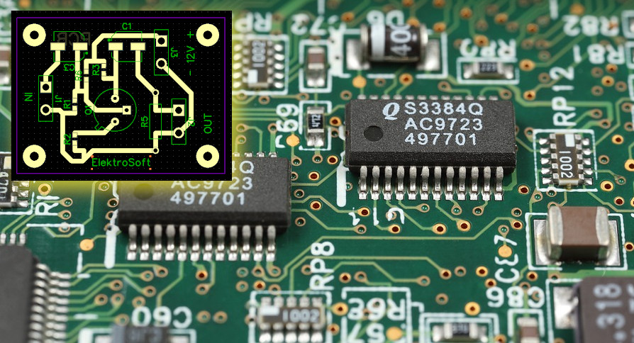
Example wiring diagram
Figure 1 shows the wiring diagram of a transistor amplifier, together with the 3D assembly. It is a promiscuous realization, with discrete components and some in SMT. The project includes the following levels, which contain elements, texts, graphics, components and more:
- Top Silk: contains the texts, labels, patterns, dimensions and references of the electronic components, on the upper side;
- Top Mask: this is the "solder mask" level and is generated on the basis of the pads;
- Top Paste: it is a level usually used for SMT pads;
- Top (signal): contains the copper tracks of the upper side;
- Board Cutout: defines the physical shape of the PCB outline. It is also used to create the 3D shape of the printed circuit board.
Since the circuit has been designed to be built only on the upper face, the "Bottom" levels have not been used.
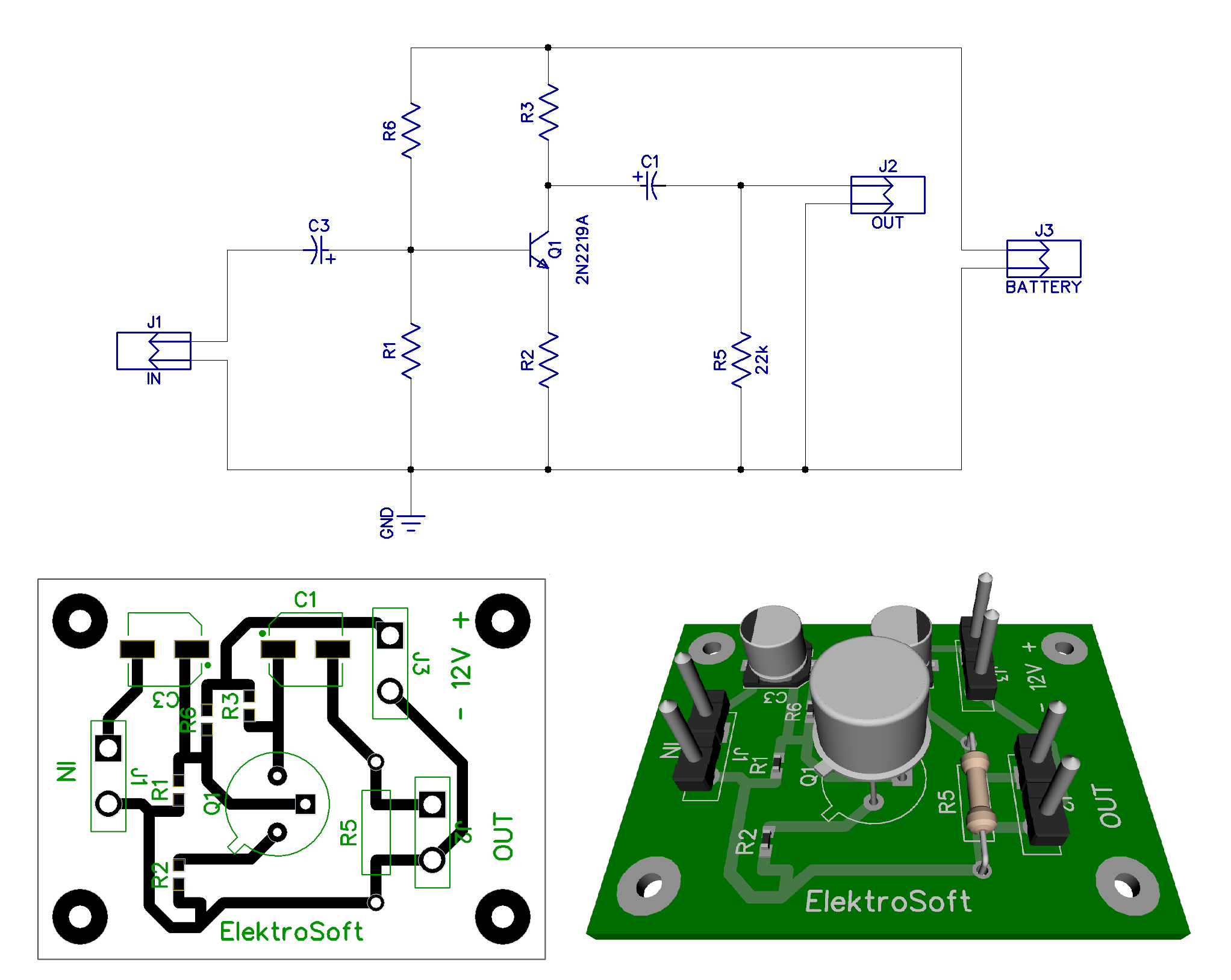
Figure 1: Wiring diagram of a transistor amplifier and its assembly.
Top Silk
The contents of this paragraph are also equivalent to the "Bottom Silk" level. As mentioned above, this level shows the elements related to the texts, labels, patterns and dimensions of the components and the screen printing in general, on the upper side of the board (see figure 2). The exported file will have the extension ".gbr", for example TopSilk.gbr. The content of the exported file contains a particular encoding that perfectly describes the elements of the upper level. The portion of the content of the file has been deliberately divided into several columns, for visibility and readability reasons.
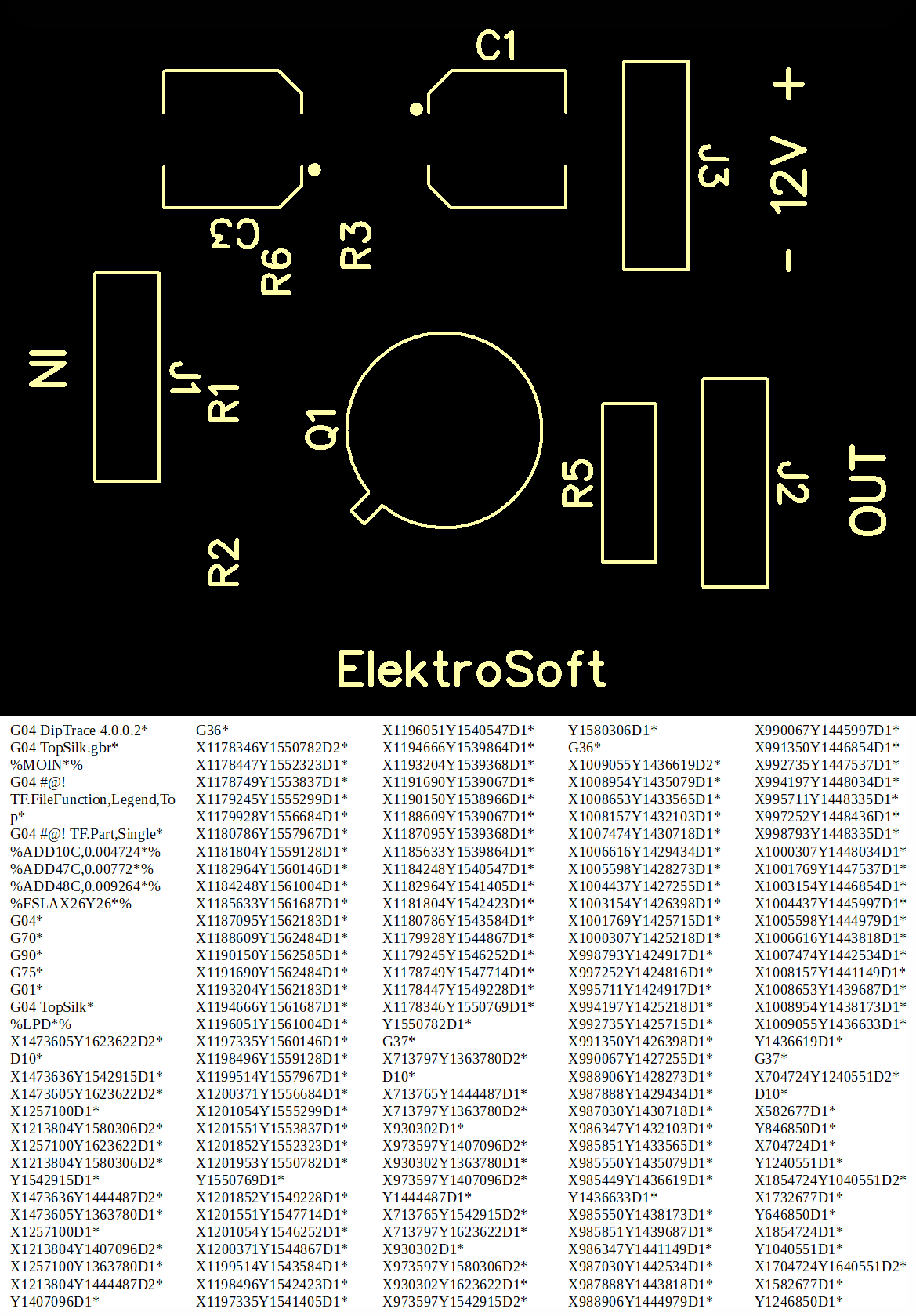
Figure 2: The Top Silk preview together with its textual codin.
Top Mask
The export function creates the "TopMask.gbr" file. Refers to any protective paint to be applied. Obviously it is possible to change the name of the target document, but it is recommended to keep the one proposed by the system. The content of the exported file (see figure 3) contains an encoding of the selected level.
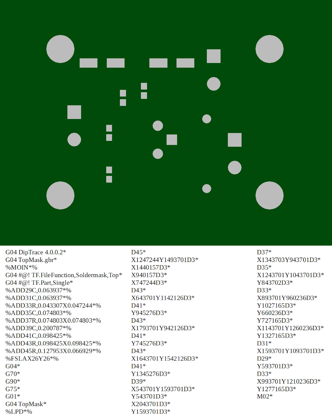
Figure 3: The Top Mask preview together with its textual coding.
Top Paste
It refers to the use of SMT components. The export function creates the "TopPaste.gbr" file. Obviously it is possible to change the name of the target document, but it is recommended to keep the one proposed by the system. The content of the exported file (see figure 4) contains an encoding of the selected level.
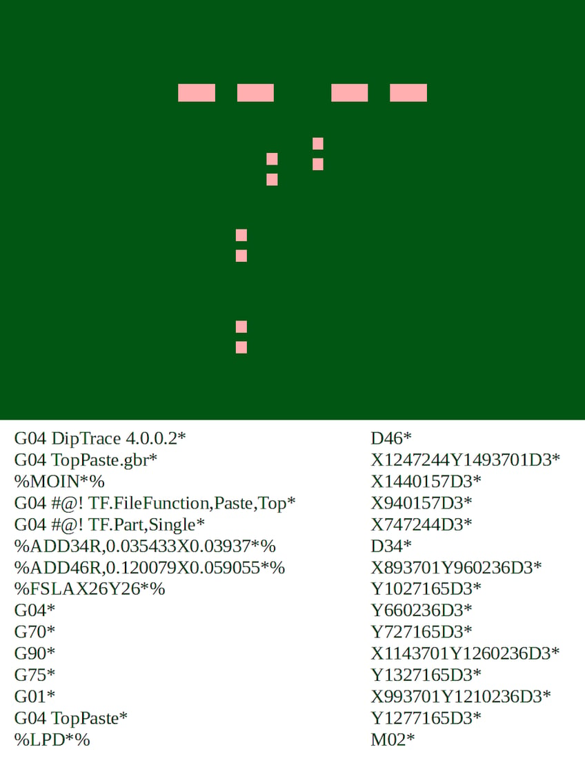
Figure 4: The Top Paste preview together with its textual coding.
Top (or Top Copper)
This is one of the most useful and interesting levels because it contains the PCB track layout, generated by automatic or manual routing (see figure 5). The same procedure is followed on the Bottom level. As can be seen on the pitches there are no holes, as they are exported to a different file and machined or not by the company, at the customer's request. The name of the file in question is "Top.gbr".
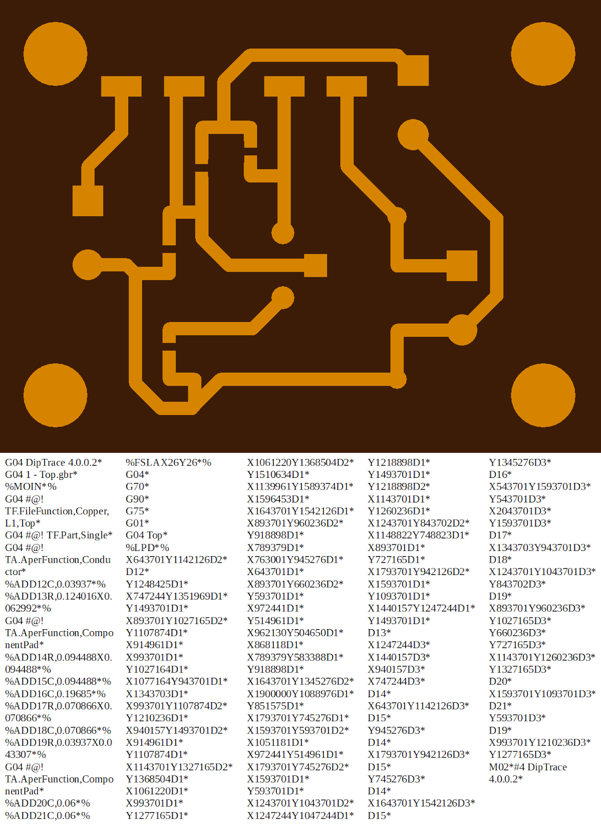
Figure 5: The preview of the tracks together with the relative coding.
Drill
This is the document for the description of the drilling specifications (figure 6). An example of a file name would be "Plated Through.gbr". Not all holes are characterized by the same diameter and some can be metallized. Depending on the type of hole, the marks on the preview also change. Even if the elements are not numerous, Gerber encoding is equally complex. PCB drilling is carried out on customer’s request, professional and fast CNC mediance.
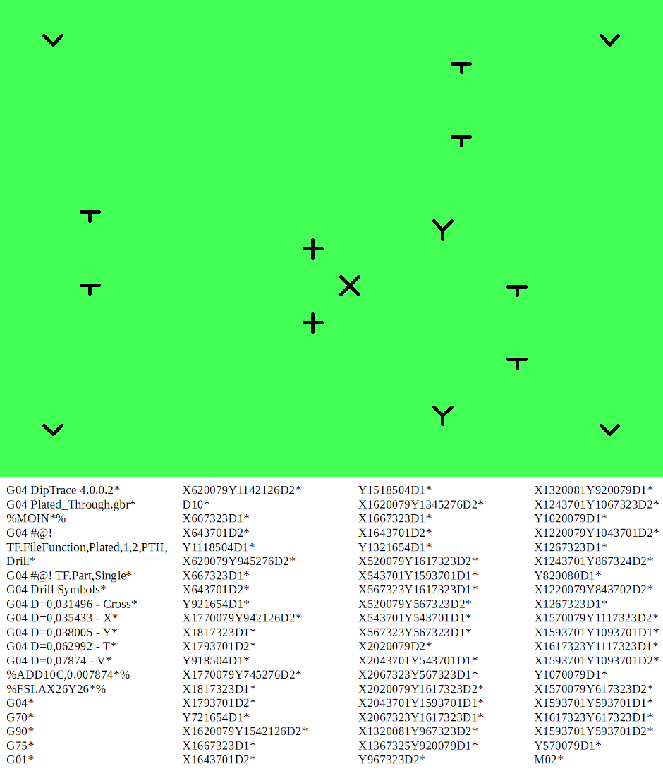
Figure 6: The preview of the drilling plane, together with its coding.
Board Outline
It is probably the simplest Gerber file as it only contains the PCB outline (see figure 7). The printed circuit doesn’t nececessarily always have to be rectangular or squared. It could also be characterized by a different shape and could even be circular.
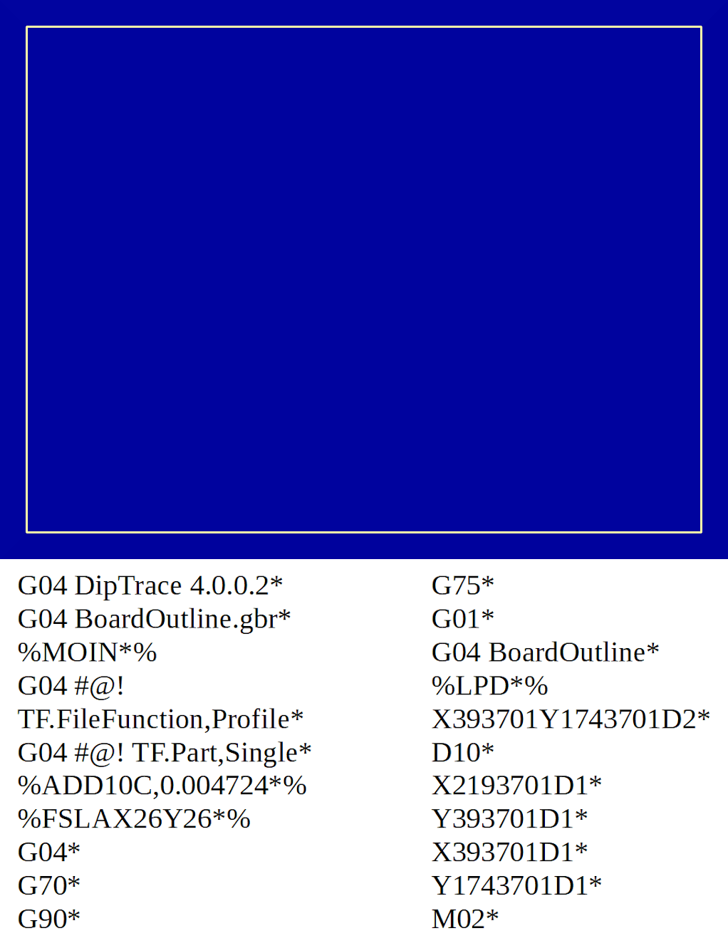
Figure 7: The preview of the PCB outline, together with its coding.
PCB manufacturing companies are equipped with extremely sophisticated and large machines (see figure 8). The CNCs used can perform all the tasks together or the more sophisticated models are dedicated to a single procedure. These machines, also equipped with processors, can directly decode the customers' Gerber files and immediately proceed with the PCB manufacturing processes, without the need to be connected to a computer. Other types of equipment, always following the directives of the Gerber specifications, have the possibility of carrying out checks on the circuits produced and performing automated optical inspections (AOI).
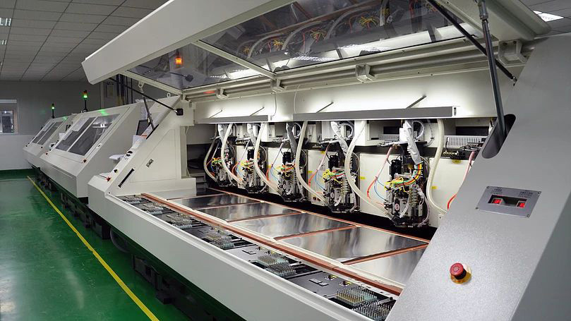
Figure 8: The most recent machines can read and execute the commands contained in the Gerber files.
Use of texts and fonts for Gerber export
Texts and writings are a fundamental element for your PCBs. They are intended to show labels, brands, terminal functions, various directives and, moreover, give a touch of class to the printed circuit board (see figure 9). Many PCB manufacturers advise their customers to follow some strategies for the
best result. Some recommend the use of "VECTOR" fonts, since they are directly exported to the Gerber file, without tampering and modifications. The "True Type" characters, on the other hand, could cause some incompatibility problems. Even Some manufacturers do not accept textual objects on the "copper Layers". Companies must always be consulted, perhaps by phone or by email, to clarify the problem related to these aspects.
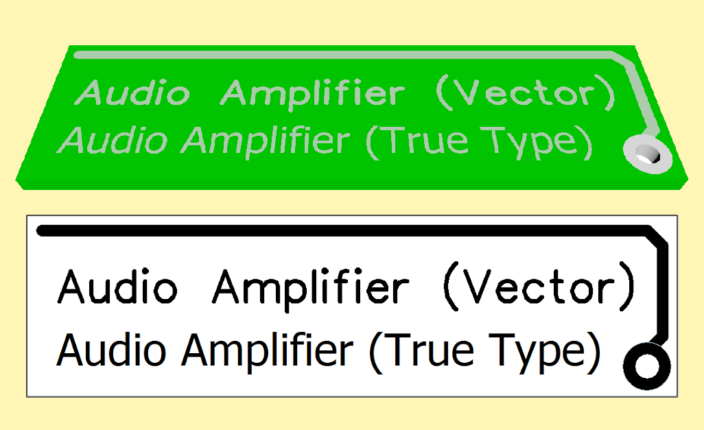
Figure 9: Although True Type Fonts are more beautiful (on your PC), but it is better to choose maximum system compatibility using VECTOR fonts.
Conclusions
Gerber files are now a standard to follow for the mass production of printed circuit boards, as they show the exact graphic description of the PCB. They should be sent to the manufacturer as soon as the project is completed and has been thoroughly checked. The designer can safely send all Gerber files produced using the export function, always with a preliminary agreement with the company. It is also possible to compress all the documents in a single zipped file, although many software automatically export to this type of archive. Many companies only accept a single compressed file. It is always a good habit to test and check your files with different Gerber viewers, before sending them to the producer. Indeed this is an excellent practice that all designers should follow. If the printing company has its own display, it is preferable to use that one, in order to match all the production results perfectly. Even if viewers use the same official RS-274X specifications, sometimes reading documents can create some incompatibilities. For maximum control, it is possible to use two, three or four different displays (see figure 10), to check and confirm the quality of the work done.
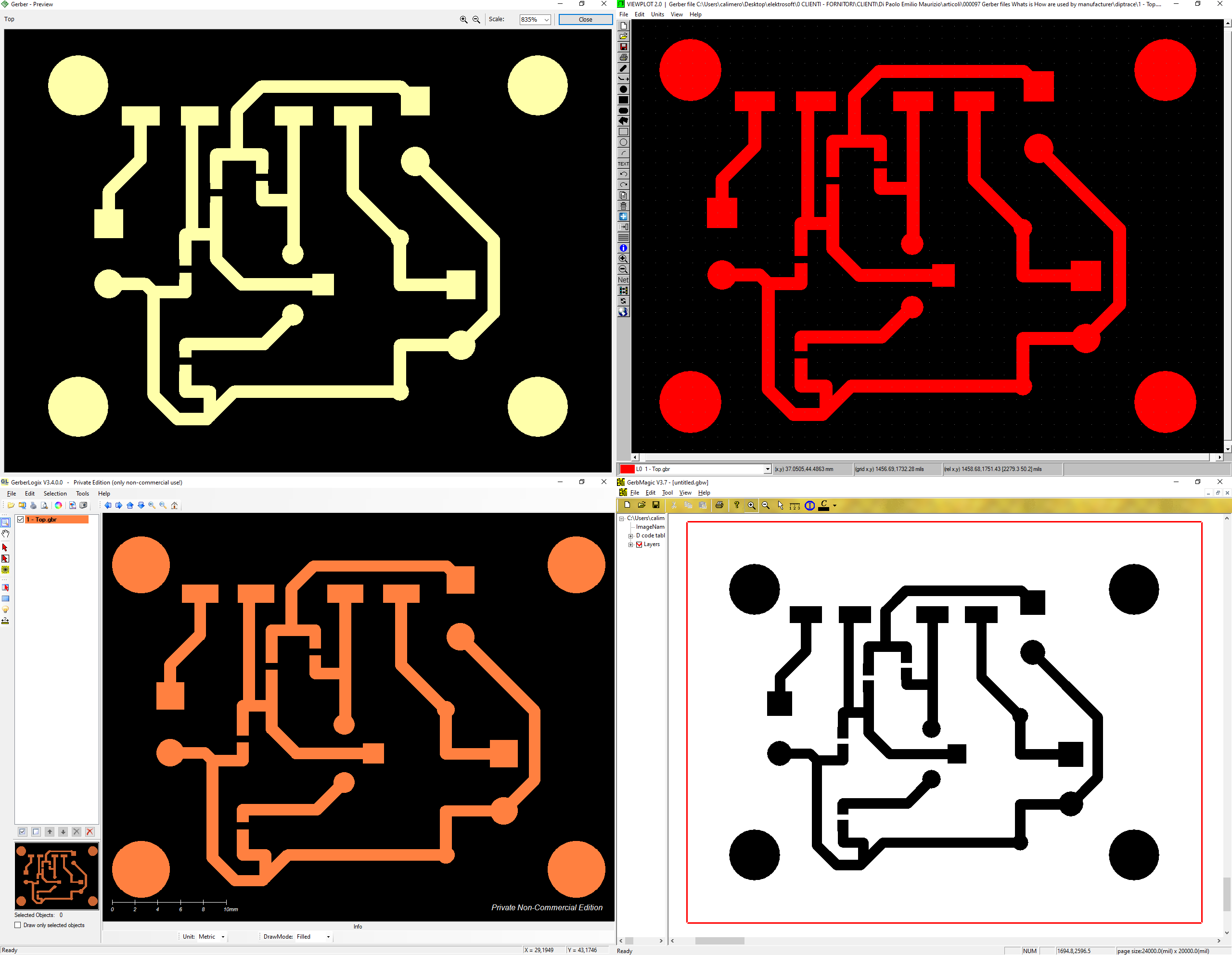
Figure 10: It is advisable to check your Gerber files with different viewers.