Dielectric materials are the basis of every printed circuit board, forming the non-conductive substrate inserted between the conductive layers of the PCB, as shown in Figure 1. Dielectric materials shall be poor conductors of electricity and provide an insulating layer between the conductive layers. As we will see in more detail in the article, one of the most widely used dielectric materials is FR-4, but there are other types of material that the designer must know and select based on the characteristics of the specific application.
The selection of the dielectric material shall be carried out based essentially on the electrical, thermal and chemical properties of the material itself.
and get your PCBA quote within the next 10 minutes!
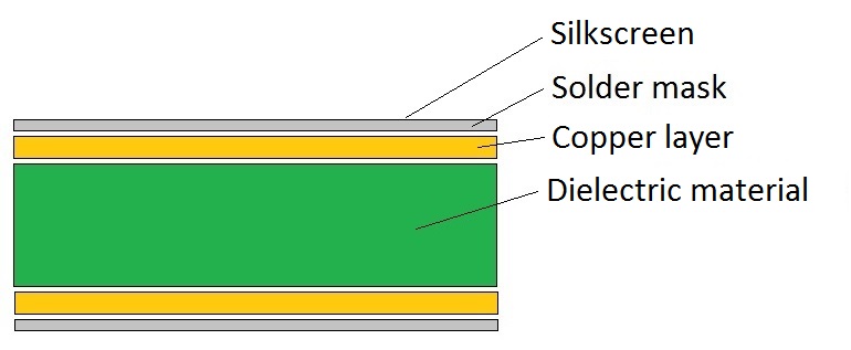
Figure 1: Basic structure of a PCB
Electrical Properties
There are two main electrical properties that shall be considered when selecting a dielectric material, namely the dielectric constant and the dissipation factor.
Dielectric constant
This parameter, represented by the symbol Dk, is also indicated by the term relative permittivity (Ɛr). The dielectric constant is a measure of the degree of electrical insulation provided by the material and is a fundamental factor for ensuring signal integrity and impedance control. Typical dielectric constant values found in dielectric materials commonly used in PCBs are between 3.5 and 5.5, but this value is strictly dependent on the signal frequency and decreases as it increases.
When designing a PCB, it is preferable to select materials with a low Dk value, which can therefore function as an insulator for the copper traces and for the power supply planes. Furthermore, the selected material should be able to keep the value of Dk as constant as possible, both as the operating frequency of the signal varies, and for the entire duration foreseen for the circuit.
To ensure reliable and stable operation of the circuit over time, a dielectric constant that remains stable over a wide range of frequencies is recommended. Figure 2 shows the trend of Dk as the frequency varies in a dielectric material expressly designed for high frequencies.
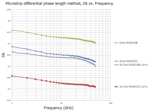
Figure 2: Dk-frequency curves for some RO4000 series materials (Source: Rogers Corporation)
Dissipation factor
Represented with the symbol Df and also indicated as loss tangent (Tan δ), this parameter indicates the ease with which a material introduces power losses. A dielectric material will lose less power the lower its dissipation factor is.
The loss tangent of the dielectric materials commonly used for the manufacture of PCBs is between 0.02 and 0.001 and its value increases with the frequency. Particularly significant in analog circuits, this parameter takes on relative significance in digital circuits, at least at frequencies below 1 GHz.
Thermal properties
When electrical currents pass through a PCB, it develops a certain amount of heat which causes thermal stress on dielectric materials, traces and components. Over time, heat can cause materials to expand, resulting in cracks, damage to tracks and soldering, or even failure.
When selecting a dielectric material, it is essential to evaluate its thermal conductivity that is its ability to dissipate heat safely without affecting the operation of the PCB. Other important thermal properties are the thermal expansion rate of the material, also known as the coefficient of thermal expansion (CTE), the glass transition temperature (Tg) and the decomposition temperature (Td).
Tg
The glass transition temperature (Tg) indicates the temperature threshold above which a material changes its characteristics when subjected to heat. More precisely, a dielectric material for PCBs softens when exposed to temperatures above Tg, and then hardens again when the heat is removed and the temperature drops.
FR-4, the material commonly used in PCBs (Figure 3), has a Tg value between 130 and 140°C. There are also materials with medium Tg (150-160°C) and high Tg (above 170°C). The higher the Tg of a material, the better its resistance to high temperatures.
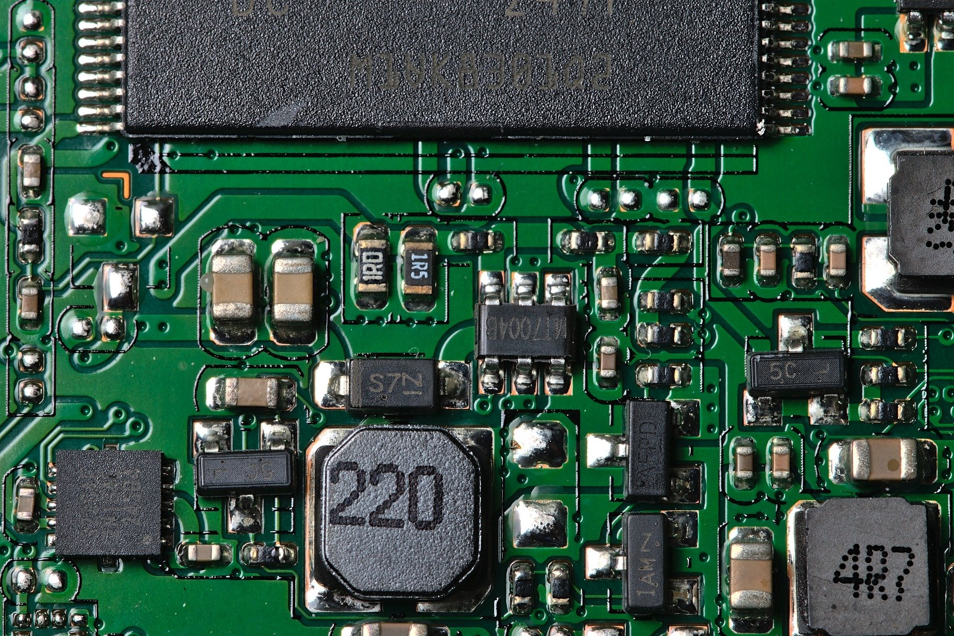
Figure 3: FR-4 is a standard PCB material
Td
The decomposition temperature (Td) indicates the temperature threshold above which the dielectric material begins to decompose. Unlike what happens for the glass transition temperature (where the material is able to recover its original properties when the temperature returns below the threshold), in the case of the decomposition temperature the effects are not reversible but permanent.
Since the temperatures reached during the soldering phase are between about 200°C and 250°C, it is preferable to select a material with a Tg below this range and higher than Td.
CTE
The coefficient of thermal expansion (CTE) indicates the rate of expansion of a material exposed to temperatures above its Tg. Measured in parts per million (ppm), the CTE is generally between 10 and 20 ppm along the X and Y axes. The CTE value should be minimized in order to prevent the PCB material from expanding on the plane X, Y.
K
Thermal conductivity (k) expresses the ability of a material to transfer heat. In most dielectric materials, the thermal conductivity (measured in W/mK or in W/m°C) is generally included in the range from 0.3 to 6W/mK. Conversely, copper has a thermal conductivity of 386W/m°C and is therefore able to transport heat faster than a dielectric material.
Chemical properties
In general, it is preferable to select materials that have low moisture absorption and high chemical resistance; in particular, a high resistance to methylene chloride. Also very important is the selection of materials with flame retardant properties, capable of resisting flames for several seconds (an example is FR-4, a material with Level 4 flame retardant properties).
Moisture absorption expresses the ability of a dielectric material to resist immersion in water. Most dielectric materials used in PCB fabrication have a moisture absorption value between 0.01% and 0.20%.
The resistance to absorption of methylene chloride is instead an index of the chemical resistance of a dielectric material. This property, measured by the MCR (Methylene Chloride Resistance) index, generally has values between 0.01% and 0.20% in most materials.
Selection of materials
The main materials that can be used as dielectrics in the manufacture of a PCB will now be examined.
FR-4
FR-4, acronym for flame retardant level 4, is today the standard material used for the manufacture of PCBs. This material, made of epoxy laminate reinforced with woven glass fiber, has flame retardant properties and complies with the UL94V-0 standard.
Being the most widely used material in the manufacture of printed circuits, FR-4 is particularly convenient for high-volume production cycles. However, this material exhibits limitations in high frequency signal applications and is not suitable for dissipating large amounts of heat. Furthermore, the dielectric constant of the FR-4 is not kept constant as the frequency varies and this can generate signal integrity problems.
DPI/PPO
Thermosetting hydrocarbon laminates (DPI and PPO) offer good mechanical stability, high durability and are easy to manufacture. In addition to excellent chemical resistance, these dimensionally stable materials have a high resistance to temperature and represent an ideal solution for all applications with heat resistance up to 110°C and high impact resistance over a wide range of temperatures. Moisture absorption is very low and the material also supports direct contact with boiling water.
PTFE
Polytetrafluoroethylene (PTFE) materials are proposed as a valid alternative to the more common FR-4. Obtained with a compound of carbon and fluorine, PTFE has a high glass transition temperature (about 120˚C).
PTFE has excellent dielectric properties which remain so even at very high frequencies, making it a suitable solution for high speed, high frequency, microwave and high power RF applications. Signal loss is very low, impedance control is simplified, and signal performance is excellent.
Polyimides
Polyimide materials are usually used to make the flexible layers in flexible and rigid-flexible PCBs, as they can be easily bent and rotated around components without compromising the operation and performance of the circuit. Polyimide also offers excellent high temperature resistance, good heat dissipation, moisture and chemical resistance.
CEM-1, CEM-2 and CEM-3
CEM is a family of PCB materials listed by NEMA that includes three categories of materials: CEM-1, CEM-2 and CEM-3.
Given its low cost, CEM-1 is the most widely used material for single-sided PCB fabrication. It is a composite material made with a combination of cellulose (paper) and a single layer of fiberglass interwoven epoxy resin (FR-4). This material does not support the application of through-hole plated holes and therefore can only be used for single-layer PCBs. Like FR-4, CEM-1 is also fireproof, but the mechanical characteristics are lower due to the greater fragility of the material.
Figure 4 shows a PCB made with CEM-1 material (note the typical whitish color of the same).
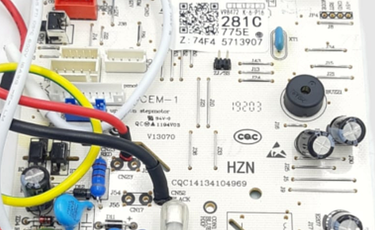
Figure 4: Example of PCB CEM-1
CEM-2 materials offer higher glass transition temperatures than CEM-1 and are composed of a cellulose paper core and a woven glass fiber surface. CEM-3 materials are glass epoxy compounds widely used for double-sided PCBs with plated holes.
Rogers
Rogers materials, produced by the Rogers Corporation company, offer several advantages over traditional dielectric materials, such as lower power losses and lower dielectric losses, better thermal management, wide range of dielectric constant values (from a minimum of about 2.55 to a maximum greater than 10), better impedance control. Although the cost is higher, Rogers materials are widely used in PCBs for RF and high frequency applications.
Metal Core PCBs
Metal Core PCBs, also known as MCPCBs, contain a metal core whose function is to redirect heat away from the hottest components. The core is usually composed of a metal plate of a certain thickness made with aluminum or special alloys. Aluminum is typically the cheapest option considering thermal conductivity, stiffness, and cost. The thickness of metal cores is typically between 30mil and 125mil, but thicker or thinner cores can be made.
The main difference between an FR-4 PCB and an MCPCB is the dielectric material with high thermal conductivity present in the MCCPB, which acts as a thermal bridge between the components of the integrated circuit and the supporting metal plate. Figure 5 shows an example of MCPCB for power lighting applications.
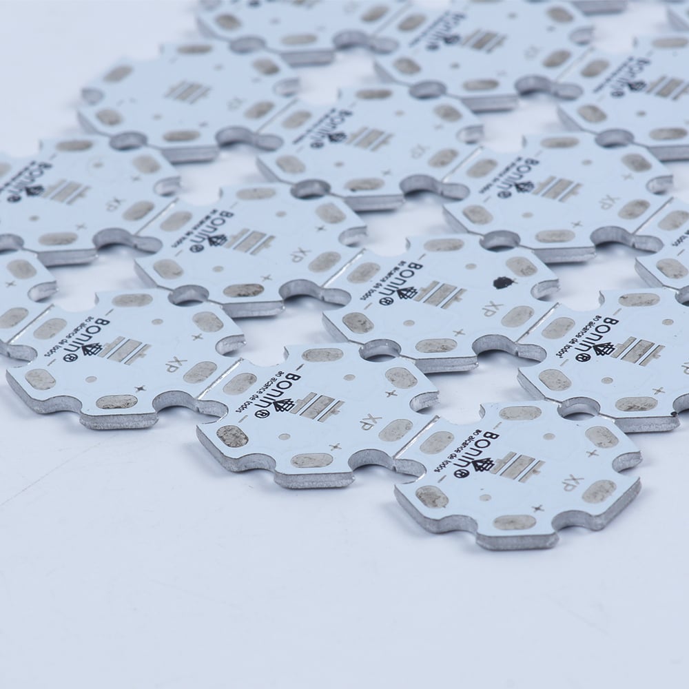
Figure 5: Example of MCPCB
Selection criteria
The selection of the most suitable dielectric material depends on the requirements of the specific application, such as voltage and current levels, maximum frequency of signals, power developed by the components, amount of heat to be dissipated.
The following guidelines can help the designer at this stage:
- Use materials with very similar dielectric constant. If you use materials with very different values of Dk, you can create problems of signal integrity and anomalous behavior when the frequency varies
- Use materials with very similar coefficient of thermal expansion (CTE). If this does not happen, the materials could expand with different rates or to a different extent with respect to the two axes X and Y, causing possible damage to the PCB and affecting the Dk value
- Make sure that the dielectric materials produce perfectly smooth and smooth surfaces, so as not to alter the Dk value
- Always look for the right compromise between budget and performance. The FR-4 is an excellent material for many applications, while in specific cases (such as high frequency RF applications, power LEDs or HDI circuits, to name a few) it is necessary to focus on materials with higher performance, even if more expensive.
Choosing the correct dielectric material allows for the creation of reliable PCBs capable of guaranteeing the same level of performance over time and with varying electrical and thermal conditions to which the circuit is subjected.
Conclusion
Performance offered by a PCB, as well as its reliability and duration over time, strictly depends on the types of dielectric material used for its manufacture. The thermal, electrical, chemical and mechanical properties are essential parameters for the selection of a dielectric material and, therefore, shall be appropriately considered in the design phase in order to guarantee the optimal operation of the printed circuit and of the electronic device in which it is used.
15.12.2022