In low frequency, the arrangement of the electronic components on the printed circuit can be carried out with greater freedom and ease. The only critical issues to follow are the final design and heat dissipation. In high frequency, however, their location is of fundamental importance and an incorrect positioning, even if electrically valid, would compromise the functioning of the entire system.
The positioning of the electronic components on the PCB is the fundamental part of any project. Many engineers often bypass this phase, relegating it, perhaps, to moments following the solution to other problems. In high frequency, the need for good positioning is greater, as it is important to optimize signal paths and improve circuit operation. Today, the best placement of components on a board is not only the result of strict theoretical rules of electronics and it is greatly facilitated and aided by a powerful software that supports designers in the creation of very sophisticated electronic circuits. The most general rules should concern the reduction of the length of the critical paths, the physical separation between the power and decision circuits and the distinction of the analog parts from the digital ones. A careful arrangement contributes to an increase in the efficiency of the circuit, also reducing its physical size.
Positioning of high frequency components
When electrical signals exceed the frequency of 1 MHz, the system becomes extremely critical, in particular as regards the positioning of the electrical and electronic components, especially the capacitive and inductive ones. The components, even when electrically connected to each other, behave differently according to their arrangement, the shape and the size of the electrical connection. Sometimes it is enough to move a capacitor or an inductance a few centimeters to totally change the behavior of the electronic circuit. This is the case with radio transmitters and receivers, HF amplifiers and other equipment that works with high frequencies. Remember that when the latter are in the order of Mhz, the signals leave the electrical circuits and spread in the surrounding space. Even a very small variation in the wiring and connections affects (in a positive or negative way) the operation of the device. Figure 1 demonstrates this criticality through a small high frequency electrical circuit. Especially in these types of circuits and solutions, the ground points should be placed close to the components, in order to avoid the formation of long signal lines that would compromise the proper functioning of the HF system. The terminals of the electronic components should not be very far apart, especially in the ground points, because unwanted auto-oscillations could easily occur. On the contrary, the components should be connected, if possible, to a single ground plane.
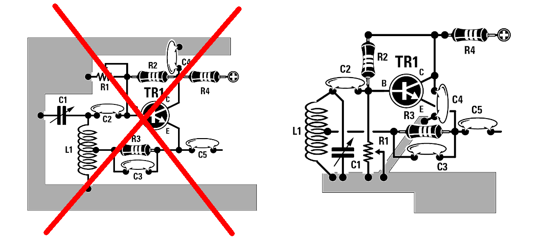 Figure 1: In high frequency circuits the ground plane must be very limited, in terms of extension, and the components connected to it should be as close as possible to each other.
As for the connections between tuning and amplification elements, they should be very short, especially if the working frequency exceeds 8-10 Mhz. In the case of high frequency LC circuits, sometimes the physical rotation of an inductor with respect to the capacitor totally changes the efficiency of a circuit, although the electrical connection remains the same (see figure 2).
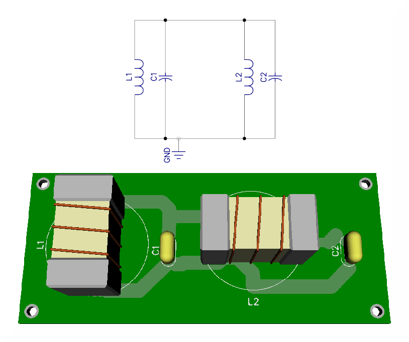
Figure 2: In high frequency it is not enough that the reactive components are electrically connected, but they must be arranged together in the correct way.
For the positioning of the resistors it is also necessary to pay the utmost attention since, especially for the power ones, they are internally constituted by a spiral of semiconductor material which acts as an inductor. While for DC or low frequency installations this fact does not present any problem, in high frequency it is an aspect to be considered with great accuracy.
Placing components for heat dissipation
Optimizing a PCB and positioning electronic components is always a delicate and demanding activity (see figure 3). The general rule states that the tracks that connect the various elements (resistors, capacitors, inductors, integrated and others), should be extremely short with devices very close together. This is true when operating mainly in high frequency. However, minimizing the length of the connections could create thermal problems, causing an uneven accumulation of local heat and causing unexplained faults at first sight. In these cases it is preferred to adopt parallel positioning of the components and thermal ducts in the circuit. The current approaches also provide rapid methods for determining an optimal positioning of the components obtaining, in fact, a uniform distribution of the heat flow. The resulting advantage is a better thermal performance of the whole system.
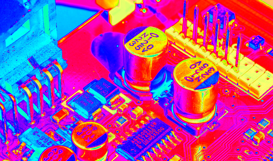
Figure 3: The measurements of the operating temperatures and the thermal simulations contribute to a good positioning of the electronic components.
It is also useful to approach the exquisitely scientific aspect of the problem, through the use of equations. A mathematical model for the performance of each individual component is considered, describing the air temperatures on an electronic board. The board consists of a grid with thermally active elements that generate heat but, at the same time, are cooled through a forced flow of fresh air by convection. The models provide equations for component temperatures and air. Linear mathematical models generally give excellent results. The model used helps to find the optimal positioning of the electronic components on a board, in order to decrease the general temperature of the system, with an increase in performance and reliability. Under normal conditions the models converge in a single steady state of temperature. Relative optimization aims to minimize the maximum board temperature.
Placement of components and Genetic Algorithms
With the advent of artificial intelligence, this electronics sector is also widely involved. There are implementations of Genetic Algorithms for the optimization of the positioning of the electronic components, especially for the evaluation of the thermal degree during operation (see figure 4). Initially they are placed on a surface and convection cooled by forced air flow. The thermal model is two-dimensional. The algorithm, therefore, optimizes the position and spacing by following different thermal criteria. In the following phase, the genetic algorithm is used to optimize the position of the electronic components on a PCB following, this time, a three-dimensional thermal model. For this kind of optimization, the software performs millions of permutations and combinations until the best arrangement is found.
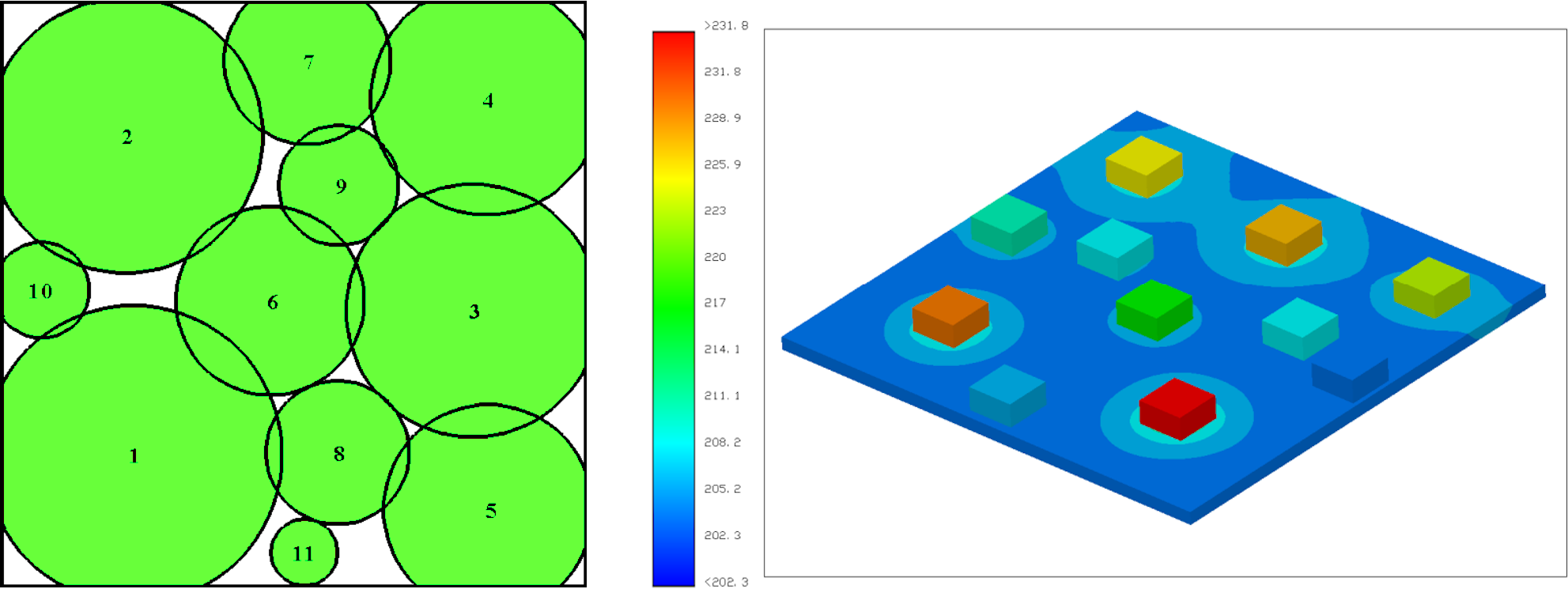
Figure 4: Genetic Algorithms help a lot in optimizing the position of the components on the PCB
Conclusions
There is absolutely no better positioning of electronic components on a circuit. It depends on many factors such as the operating frequency, the power and current in circulation, the expected operating temperatures and many others. Today, calculation tools have been developed that quickly provide excellent component positioning with a uniform heat flow distribution. The most sophisticated tools are based on genetic algorithms that use different combinations of solution strategies. It is expected that these types of approach can be used in a wide variety of applications, such as space, automotive and energy supplies in general.
and get your PCBA quote within the next 10 minutes!